Electromagnetic logging

Electomagnetic Survey for Rig Floor Tubing Inspection (EMI)

The Electromagnetic Inspection log designed to inspect production tubing’s on the surface on the Rig Floor (on Rotary Table), while the pipe string is being pulled from the well, with continuous monitoring and in real time. 


The equipment is easily raised and placed on the rotary table by means of the line of lifting of tools (Winch) and positioned on the wedges of such form, that the technician can observe the operation of the wedges.

Electromagnetic Scanner

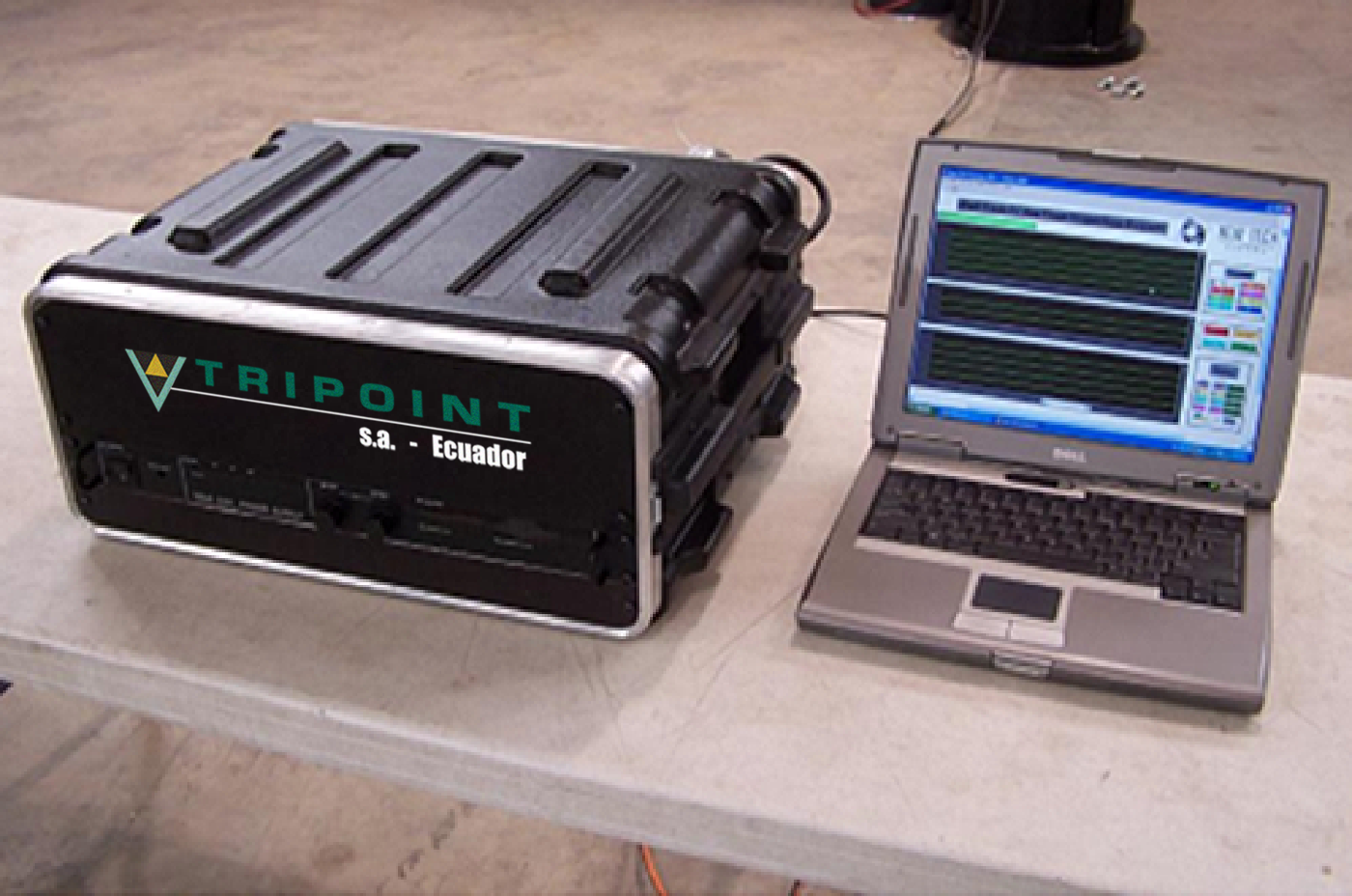
Electromagnetic logging provides a fast tubing calibration at the job site, with reliable results, delivering high quality tubing inspections to quickly return the well into production and giving customer satisfaction the true condition of the tubing string.

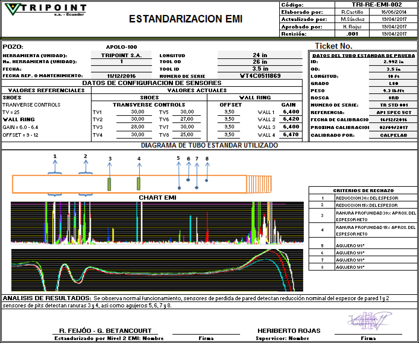
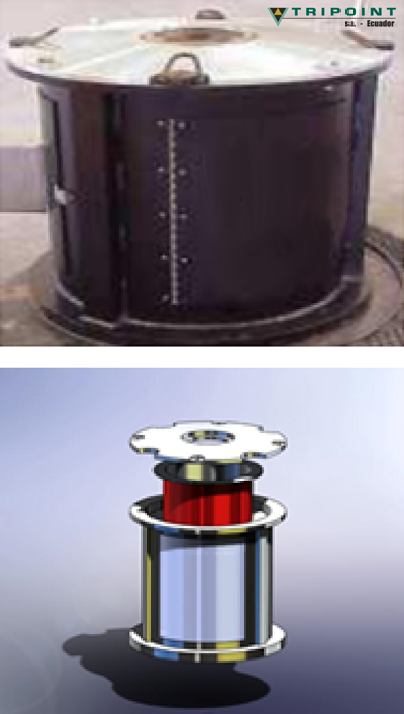
The principle is based on the induction of electric current that generates through the wall of the pipe, which generates a magnetic field that determine the state of the walls of the tubing of 2-3/8'', 2-7/8 ", 3-½", 4-1/2 " sizes.

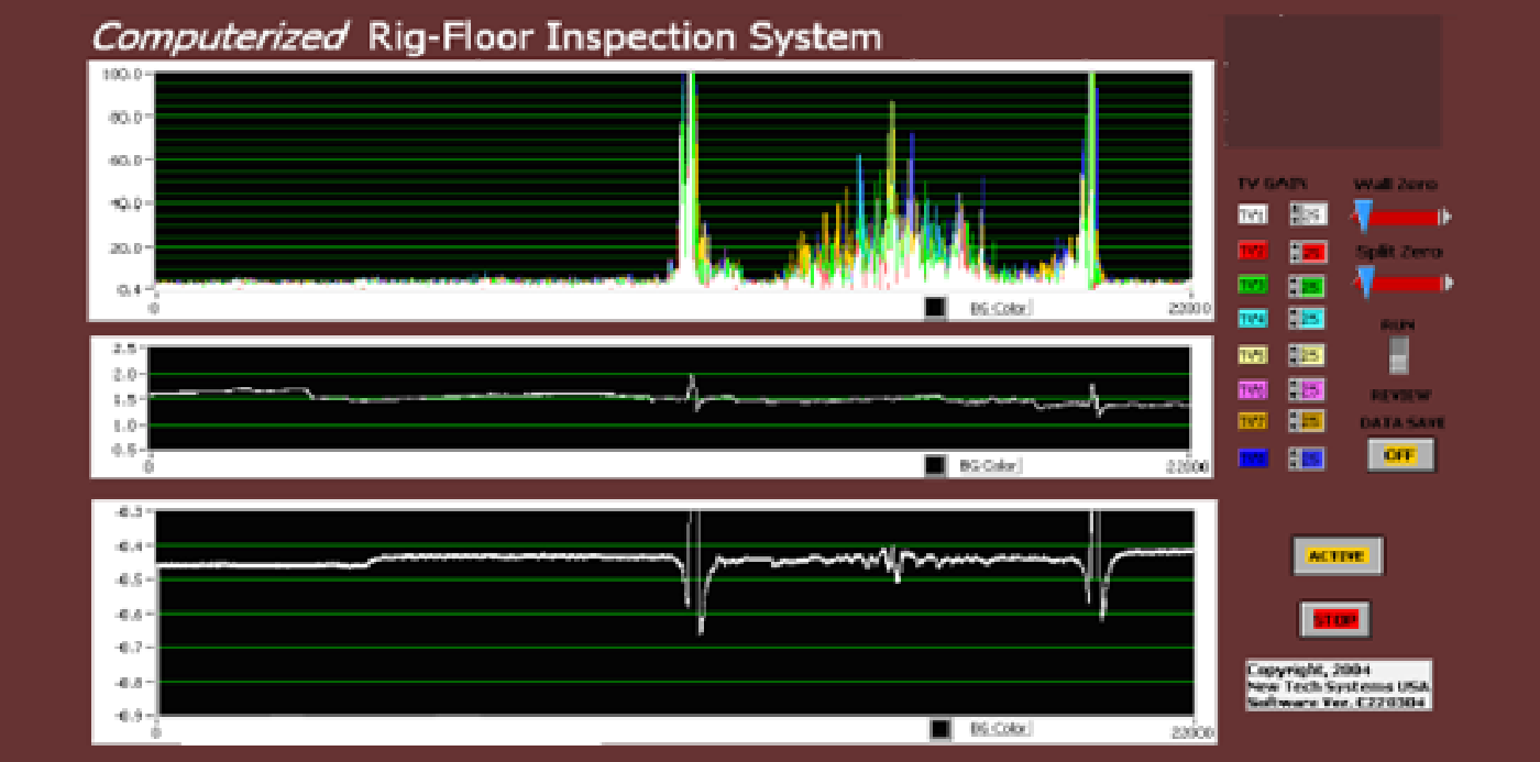
It has the necessary equipment for the detection of discontinuities or transverse defects such as pitings, cracks, loss in nominal wall thickness due to corrosion and any other discontinuity or defect that can be found in the pipe body excluding the threads and connections.

Console & Software

The tool is placed on the rotary table and on the slips allowing the normal outlet of the pipe string from the well at high speed (up to 250 ft / min).

On the screen of the computerized electronic system, the tubing is monitored pipe by pipe as they are pulling out of hole and passes through the scanner ystem, determining the range and which color code corresponds to each one.

As we can see in the top figure shows the high peaks at the left and at the right corresponding to Couplings gaps , the low readings (low picks) close to couplings determine a minimum material wear on the wall of the pipe, while the high readings in the center indicate strong material wear in the wall at the center of the pipe.

System Features:

• Electronic-PC system with presentation in digital signal.

• Solid system for monitoring pipe wall.

• Three-dimensional system for detection of defects in pipes.

• Detection of transverse cracks, pitting, longitudinal defects, cracks, corroded wall losses, wear on rods, etc.

• Remote calibration mechanism (wireless).

• Allows maximum pulling velocity from well (up to 250 ft / min).

• Real-time inspection review and reporting.

• Capacity to Inspect: Sizes 2- 3/8 ", 2-7/8", 3-1/2 ", 4-1/2".

• Inspection Speed Range: Up to 250 ft / min.

• Estimated Time for Tool Calibration: 10-20 minutes.

• Free system of any type of Gamma radiation.

The pipeline is selected and properly color-coded as it is pulling out of hole according to API color-code for pipes:

Calibration and Standardization of EMI Equipment

After each service the EMI equipment is disassembled and subjected to the complete maintenance of all its components. Subsequently, the equipment is assembled, tested and calibrated in our workshop using "Pattern" tubes of various sizes. Into those patterns were manufactured “damages” like pitting, cracks, wall loss and holes.

As a result of these tests, the Calibration and Standardization of the equipment is obtained and the respective Calibartion and Standardization report is elaborated as the attached to guarantee a perfect state and operation of the equipment / tools for each service of Pipe inspection at wellhead with EMI system and equipment.